Back to Articles

Normally Open vs. Normally Closed: Choosing Contact Logic for Control Systems
A cut wire behind a control panel should stop the machine, not quietly disable the button an operator reaches for when something goes wrong. Which of those two things happens comes down to a decision designers make early: whether each switch, relay, or sensor output sits open or closed when nothing is acting on it. Engineers call those two states normally open (NO) and normally closed (NC), and choosing the wrong one produces circuits that pass every bench test and then fail dangerously in the field.
A normally open contact blocks current in its resting state and passes current only while something actuates it. A normally closed contact does the opposite, carrying current at rest and interrupting the circuit when actuated. "Normally" describes the de-energized, unactuated shelf state of the device, not the state it happens to spend most of its runtime in.
That resting-state definition trips up designers who reason from how a machine behaves during production. A doorbell button is the clean NO case, because pressing it completes the circuit and releasing it breaks the circuit again. The plunger switch in a refrigerator door is the NC case: nothing presses the plunger while the door hangs open, the contact stays closed, and the lamp lights. Closing the door actuates that contact open. In both examples, the label comes from what the component does sitting on a shelf with no power and no mechanical input.
How Do NO and NC Contacts Differ in Practice?
The two contact types differ in four ways that matter to a panel designer: what they do at rest, what current they draw in that state, how they behave when the wiring fails, and which applications suit them.
| Dimension | Normally Open (NO) | Normally Closed (NC) |
|---|---|---|
| Resting state | Open, no current flows | Closed, current flows |
| When actuated | Closes the circuit | Opens the circuit |
| Current at rest | None through the contact | Continuous through the loop |
| If a wire breaks | Circuit stays open, actuation does nothing and the fault stays hidden | Circuit opens, which reads as an actuation |
| Typical uses | Start buttons, pushbutton-triggered relays, presence detection | Emergency stops, safety interlocks, limit switches, fault loops |
The broken-wire row does most of the work in a real design review. A failed NO circuit fails silent, meaning the operator presses the button and nothing happens, with no indication of why.
A failed NC circuit fails loud, because the machine reacts as though someone actuated the device. Designers pick between those two failure modes rather than between two normal behaviors.
Emergency stop circuits use NC contacts so that a broken wire, a loose terminal, or a lost supply produces the same outcome as pressing the button. An NO e-stop would leave a machine running with a severed wire, and no one would find out until an operator needed the
button and it did nothing.
Failsafe behavior depends on more than the contact type alone. Safety-rated e-stop devices use direct opening action, a mechanical arrangement that forces the contacts apart through the actuator itself instead of relying on a spring, so a welded contact still separates when the operator hits the mushroom head. IEC 60947-5-1 describes that requirement for control circuit devices, and ISO 13850 covers the emergency stop function at the machine level.
Wiring an e-stop through a standard PLC input also falls short of what most machinery safety assessments call for. Panel builders route those contacts through a safety relay or a safety- rated controller, which monitors both channels of a dual-contact device and detects a short between them. The NC contact is the starting point for failsafe design, and the monitoring circuit is what makes it hold up.
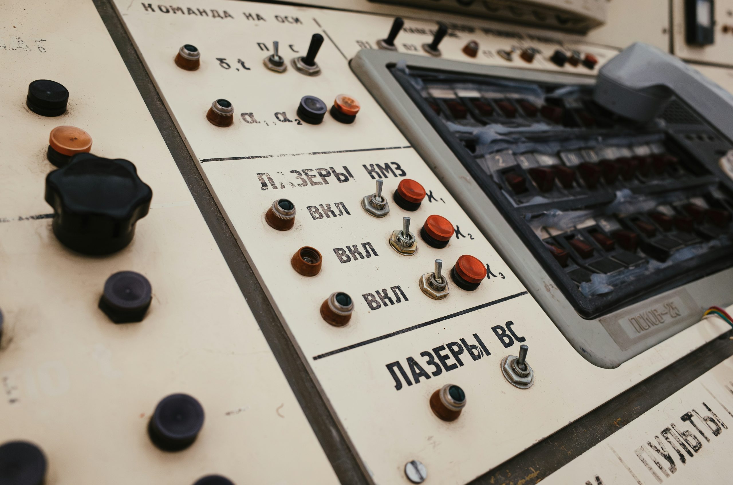
How Does a PLC Read an NC Contact Differently Than an NO
One?
A programmable logic controller (PLC) reads voltage at a terminal, not contact geometry, so the field device’s contact type decides what a 1 or a 0 means in the program. Wiring an NC contact means the input bit sits at 1 during normal operation and drops to 0 when the device actuates or the wire breaks. An NO contact inverts that relationship.
Ladder logic instructions add a second layer that engineers routinely confuse with the first. XIC (Examine If Closed) goes true when the input bit is 1, and XIO (Examine If Open) goes true when the bit is 0, regardless of what hardware sits out in the field. For a hardwired NC e-stop, the programmer uses an XIC instruction in the rung, because the bit reads 1 while the machine is safe to run. Writing XIO there because the field device is "normally closed" inverts the logic and produces a machine that only runs while the e-stop is pressed.
Single pole double throw (SPDT) and double pole double throw (DPDT) switches package NO and NC contacts in one device, so a designer does not have to choose. An SPDT switch gives one common terminal with both an NO and an NC contact off it, the arrangement contact manufacturers call Form C. A DPDT switch provides two electrically isolated Form C sets that actuate together.
Those extra poles solve a wiring problem that shows up on nearly every panel. Engineers can run the NC side into a safety or interlock loop while the NO side drives a contactor coil, a panel indicator, or a status input on the PLC, all from one actuation and with no risk of the two circuits disagreeing about switch position. Sourcing a DPDT part early costs less than discovering mid- build that a status lamp needs a contact the switch does not have.
How Do You Test Whether a Contact Is NO or NC With a Multimeter?
A continuity test on an unpowered, isolated device identifies the contact type in under a minute.
The resting reading tells you which type you are holding.
1. Isolate the device and confirm the circuit is de-energized with a voltage test before touching any terminal.
2. Set the multimeter to continuity or to the lowest resistance range.
3. Probe the two contact terminals with the device at rest. A reading near zero ohms, usually with an audible beep, indicates NC. An open or overload reading indicates NO.
4. Actuate the device by hand and watch the reading reverse. A contact that fails to reverse points to a welded or mechanically stuck contact.
5. Repeat for each contact block on multi-pole devices, since a single actuator may carry both types.
Step 4 is also the fastest field diagnostic for the two most common contact faults. A contact that reads closed at rest and stays closed under actuation has welded, and one that never closes in either state points to a broken internal link or a corroded terminal.
Which Contact Type Should You Choose for Your Control System?
Safety requirements decide the question wherever they apply, and everything else is a design trade-off. Emergency stops, guard interlocks, and fault-detection loops use NC contacts because the failure mode has to be the safe state. Start commands, jog buttons, and presence detection use NO contacts because an accidental short or a stuck contact should not command motion.
Three factors settle the remaining cases. Energy draw favors NO for battery-powered or remote sensing, since an NC loop keeps current flowing through the sensor’s output stage whenever the system is idle. Actuation frequency favors putting the less-used state at rest, which reduces mechanical cycling on the contact that carries load current. Environment favors NC in installations where vibration, corrosion, or rodent damage make an open-circuit fault likely, because those faults announce themselves instead of hiding.
What Digital I/O Changes About Contact Logic
Sensor manufacturers now ship devices with software-selectable NO or NC output, which moves a decision that used to happen at the purchase order into a configuration screen, and IO-Link diagnostics let a controller detect a wire break on an NO channel that would once have failed silently. Those capabilities narrow the gap between the two contact types for process and status signals, where a controller can report a fault it previously had no way to see.
Safety circuits are staying hardwired anyway. A hardwired NC chain with direct opening action contacts works without firmware, without a configuration file, and without a network that might be down at the moment an operator needs the machine to stop. Engineers designing control panels today are building two parallel logic systems, one configurable and diagnostic-rich for process signals, and one deliberately simple for the circuits that have to work when everything else has failed.